Description
This reference design demonstrates the use of the RPi Camera FMC with 4x cameras and 1x DisplayPort monitor attached. The video streams coming from each camera pass through a video pipe composed of the AMD Xilinx MIPI CSI Controller Subsystem IP and other video processing IP. The cameras can be utilized through GStreamer in PetaLinux.
Hardware Platforms
The hardware designs provided in this reference are based on Vivado and support a range of MPSoC evaluation boards. The repository contains all necessary scripts and code to build these designs for the supported platforms listed below:
FPGA platforms
Target board |
FMC Slot Used |
Cameras |
VCU |
|---|---|---|---|
HPC |
2x |
❌ |
Zynq UltraScale+ platforms
Target board |
FMC Slot Used |
Cameras |
VCU |
|---|---|---|---|
LPC |
4x |
✅ |
|
HPC0 |
4x |
❌ |
|
HPC1 |
2x |
❌ |
|
HPC0 |
4x |
✅ |
|
LPC |
2x |
❌ |
|
HPC |
4x |
✅ |
Software
These reference designs can be driven within a PetaLinux environment. The repository includes all necessary scripts and code to build the PetaLinux environment. The table below outlines the corresponding applications available in each environment:
Environment |
Available Applications |
|---|---|
PetaLinux |
Built-in Linux commands |
Architecture
The hardware design for these projects is built in Vivado and is composed of IP that implement the MIPI interface with the cameras and VCU as well as a display pipeline. The main elements are:
4x Raspberry Pi cameras each with an independent MIPI capture pipeline that writes to the DDR
Video Mixer based display pipeline that writes to the DisplayPort live interface of the ZynqMP
Video Codec Unit (VCU)
The block diagram below illustrates the design from the top level.
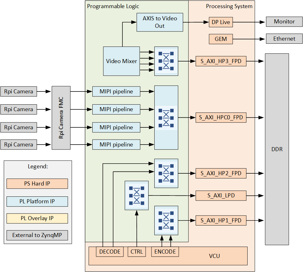
Capture pipeline
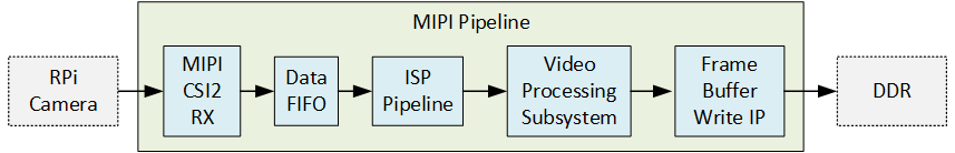
There are four main capture/input pipelines in this design, one for each of the 4x Raspberry Pi cameras. The capture pipelines are composed of the following IP, implemented in the PL of the Zynq UltraScale+:
The MIPI CSI-2 RX IP is the front of the pipeline and receives image frames from the Raspberry Pi camera over the 2-lane MIPI interface. The MIPI IP generates an AXI-Streaming output of the frames in RAW10 format. The ISP Pipeline IP performs BPC (Bad Pixel Correction), gain control, demosaicing and auto white balance, to output the image frames in RGB888 format. The Video Processing Subsystem IP performs scaling and color space conversion (when needed). The Frame Buffer Write IP then writes the frame data to memory (DDR). The image below illustrates the MIPI pipeline.
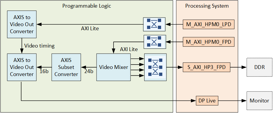
Display pipeline
The display pipeline reads frames from memory (DDR) and sends them to the monitor. To allow for four video streams to be displayed on a single monitor, the design uses the Video Mixer IP with four overlay inputs configured as memory mapped AXI4 interfaces. The Video Mixer IP can be thus configured to read four video streams from memory and send them to the monitor via the DisplayPort live input of the ZynqMP. The input layers of the Video Mixer IP are configured for YUY2 (to this Video Mixer this is YUYV8). The output of the mixer is set to an AXI-Streaming video interface with YUV 422 format, to satisfy the DisplayPort live interface.
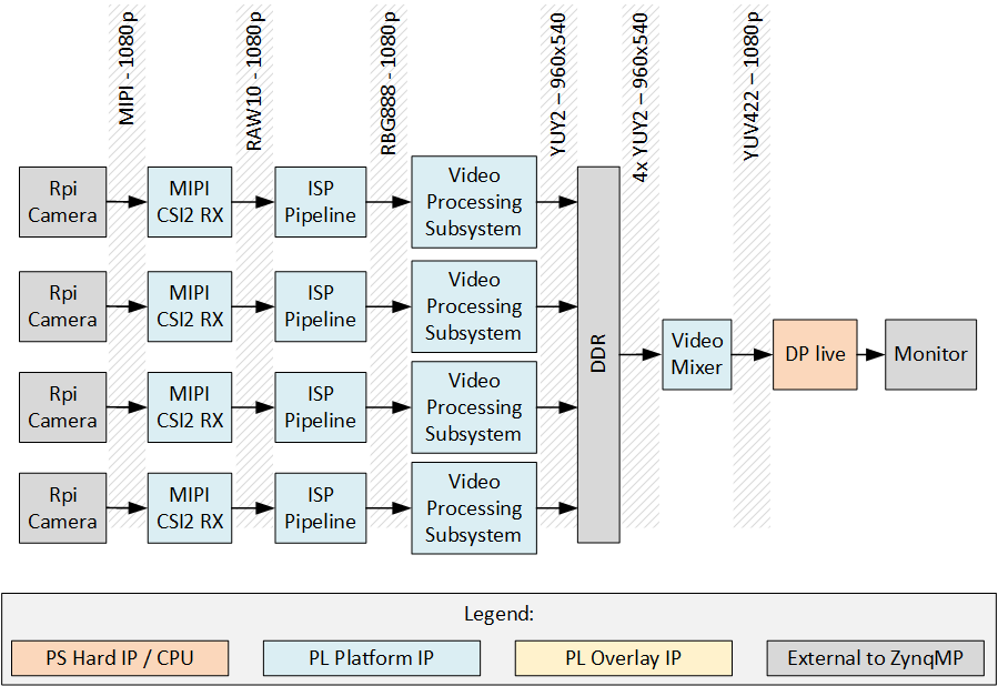
End-to-end pipeline
The end-to-end pipeline shows an example of the flow of image frames through the entire system, from source to sink. In the diagram, the image resolutions and pixel formats are shown at each interface between the image processing blocks. The resolution and pixel format can be dynamically changed at the output of the RPi camera and the scaler (Video Processing Subsystem IP).
Video Codec Unit
For some of the target boards, the Zynq UltraScale+ device contains a hardened Video Codec Unit (VCU) that can be used to perform video encoding and decoding of multiple video standards. On those target designs, we have included the VCU to enable these powerful features. Refer to the list of target designs to see which boards support this feature.